

Summary
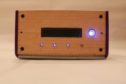
In an attempt to produce a high-quality, yet affordable, birthday present for my girlfriend, I decided to design a custom Bluetooth speaker. Six months after her birthday, it is finally done. There are plenty of Bluetooth speaker tutorials online, but I wanted to take my speaker a couple steps further.
Sunk Cost: ~$250
Allocated cost: ~$40
Build Complexity: 8/10
Design Time: 8 Months
Estimated time to complete with instructions: 20 hours
Features
The passive radiator speaker design is calibrated for an ideal transient frequency response curve and for a resonant frequency of 75 Hz.
Sound reactive NeoPixel display without using mic (utilizes custom in-line automatic gain control, AGC, circuit).
Custom battery indicator circuit.
3S 18650 battery design utilizing balanced charging (16 hours of playtime at max volume).
Reclaims a high-end speaker cheaply obtained from thrift store.
Customizable 3D printed and laser cut design which could also be produced with only a bandsaw and drill press.
Novel and ergonomic button control system.
Bluetooth connectivity, aux in, and secondary speaker line-out port.
Components
Bluetooth Digital Amplifier Board ($14.99)
I chose a TDA7492 50W*2 board but other boards will work.
If you choose this board, look for the version with an aux port.
Speakers ($7.98)
You can get high quality speakers dirt cheap by salvaging bookshelf speakers from thrift stores. I found two speakers from a from a $260 Philips MCM8 stereo system for a steal of $3.99 each.
You will need two speakers for this build.
Plywood ($13.34)
I chose a 3/16″ cherry laminate because I had it on-hand. Similar sheets cost around $14.00 from Home Depot.
Aux Extension
Wire
PLA Filament
Push Buttons
Electronic Components
Standoffs
LEDs
Buttons
Rubber Cement
Screws
Arduino Nano (Chinese clone)
NeoPixels
18650 Batteries
3S Battery Management System
The first board I ordered was DOA. It may be worth it just to order a higher end board.
3S Balance Charging Board
3s 18650 Charging Cable
Bluetooth Board and Speaker
Coming soon…
Sound and Enclosure Design
A great source for understanding speaker design is audiojudgement.com. Note that the sources cited below are three separate articles from audiojudgement written by the same author.
There are three primary types of speaker enclosures: closed, ported, and passive radiator. Sealed speaker enclosures allow for compact size and they have an excellent transient frequency response. Ported enclosures, on the other hand, are more efficient and can produce a better low-end (Tanasescu, 2016). Passive radiator speakers combine the advantages of ported and sealed by allowing a more compact design, good frequency response, and high-efficiency (Tanasescu, 2016).
Speaker enclosures are calibrated to allow air to push back against the speaker, effecting its movement. In sealed enclosures, the air is compressed like a spring when the speaker is pulled in. In ported enclosures, air is pushed back and forth in the speaker’s port (generally a long tube). The inertia of the air in the port resists movement, in turn resisting the movement of the speaker. Passive radiator speakers mimic ported speakers. However, instead of using the inertia of air, the inertia of the passive radiator’s diaphragm resists movement. (Tanasescu, 2016).
The issue I ran into was that passive radiators are generally used with large speakers or subwoofers. In order to design my enclosure, I had to design my own system for calibrating the small enclosures with passive radiators.
I designed a spreadsheet (available for free here) that can be used to calibrate the speaker enclosure for two desired specifications:
Ideal box volume, Vb, for frequency response.
Appropriate passive radiator mass to match necessary port length.
Using the Spreadsheet
0) Getting Started
Download the spreadsheet (available here) and plug in the inputs for the measurements section (left side of interface tab).

1) Desired Performance
The main performance factor you need to decide about your speaker is the resonant frequency.

I decided to base my speaker off of a JLB Charge 2+ by measuring the resonant frequency of the that speaker using Option 1: Rice Test as described below, I found the resonant frequency of the JLB Charge 2+ to be 75 Hz. This gives a good response for music by providing a nice low-end. This also helps to mitigate the steep roll off on the low end of passive radiator enclosures. However, a resonant frequency of 80 Hz would be more ideal for listening to spoken word and podcasts.
2) Speaker Measurements

There are three important measurements for a speaker. Two are easy, inner and outer diameter of the speaker diaphragm diameters.

The third thing you need to know is the speaker’s moving mass. If you are salvaging a speaker (like me), or if you bought a cheap one, you probably won’t be able to find this value. There is a cheap method
Speaker Moving Mass (inputs FS and FS1):
There is a fairly simple method to finding the moving mass of your speaker. If this isn’t documented, it can be measured using Method 2, added mass, described in Measuring Loudspeaker Parameters.
You will need to first find the free-air resonant frequency of the speaker, FS. At a speaker’s resonant frequency, the movement of the cone is at its minimum and the independence of the speaker is at its maximum. This gives us possible tests.
Option 1: Rice Test
Requirements:
Amp Board
Smartphone or Computer
Rice
By placing rice on the diaphragm of a face-up speaker, you can visually determine when the movement of the speaker is at its minimum. Add only a small amount of rice in order to reduce the rice’s impact on the speaker’s performance. Connect your amp board to your speaker and play a frequency sweep. The resonant frequency, FS, is the frequency that causes the rice to move the least.
Option 2: Frequency Generator and Oscilloscope
For those with more resources, a more accurate test is also described in Measuring Loudspeaker Parameters. Wire the circuit shown and measure the voltage across the resistor. You can use a frequency sweep on your phone or laptop and hook it up to your amp board for the speaker instead of using an audio oscillator and power amplifier. The resistor should be ~10k.

Elliot, 2014
Measure the voltage across the resistor, the frequency that causes the voltage to be at its minimum is the resonant air frequency, FS.
Finding FS1
In order to find moving mass, you can add a mass to the speaker and remeasure the resonant frequency. Add a mass (silly putty or blu-tak work well). You need to measure the added mass on a scale that is accurate to at least 0.1g. Repeat the process you used to find the free-air resonant frequency using the same method you used to find FS but, this time, with the mass attached. This will give you FS1. Enter mass added, FS, and FS1 into the spreadsheet and it will take care of the calculations.


3) Passive Radiator Moving Mass:
There are four measurements you need for the passive radiator. Inner and outer diameter are the same as described in the speaker measurements section. The moving mass of the passive radiator is measured via a different method.

The mass of your passive radiator impacts the resonant frequency of your speaker. You can calibrate this by adding mass to your radiator (this can be done by adding clay or gluing on coins). Of course, there is no way to reduce the mass of the radiator, so this needs to be considered during the design process.
The first step is to determine the mass of your passive radiator. This may be included in your radiator’s documentation. I chose to purchase cheap radiators from eBay (four radiators for $6.40), so they did not come with any documentation.

In this case, it is necessary to calculate the moving mass of the passive radiator on your own. This process will require you to ruin one of the radiators, so make sure to order an extra.
Step 1: Cut away the diaphragm from the mounting rim of the radiator. Measure the mass of the diaphragm.
Step 2: Cut the rubber lip from the rigid portion of the diaphragm. Remeasure the mass.
Step 3: Enter the total and inner masses into the spreadsheet. It will interpolate for the actual moving mass value (add 1/3 of the rubber lip mass to the rigid center mass). This accounts for the rubber lip less than the distance that the rigid center moves. This gave me a moving mass of 13.18 g, but you don’t need to worry about that part.


4) Wood Thickness

The design for my speaker utilized two thick side plates, onto which the top, bottom, and side plates would be attached. For this to work, I needed my side plates to be thicker that the top, bottom, and sides. Input the thicknesses into the spreadsheet.

5) Component Dimensions
The spreadsheet will help you determine the minimum dimensions of your enclosure so that you can fit all of your passive radiators and speaker’s in the enclosure.

The spreadsheet makes two assumptions:
All speakers are mounted on the front of the speaker.
Passive radiators are mounted on either the side or back of the enclosure.
Enter the dimensions of your chosen speaker(s) and passive radiator(s) into the spreadsheet.
6) Component Volumes
In order to calculate the internal volume of the enclosure, you will need to estimate the volumes of all the additional components in the enclosure.

7-9) Designing the Enclosure
Now that the basic measurements are complete, you can begin on the design portion of the spreadsheet in the right-hand column.
Watch the “Checks” portion of the spreadsheet. You want a low Volume percent error (actual volume is close to desired volume) and a positive or very slightly negative value for Mass to Add to Each PR (you can add mass to radiator, but it is difficult to remove mass).

In the case above, the green-filled cells indicate that the enclosure design is good. Yellow or red cells indicate that something could be improved.
Start with the dimensions of the enclosure. Yellow cells are the best ones to play around with in order to fine-tune your enclosure.

Artist: Skylar Spence, Track: Fiona Coyne
Circuits
There are three circuits for this project, two for the spectrum analysis lights and one for the battery level indicator.
Full circuitry drawings coming soon.
Spectrum analyzer:
Circuit #1: Automatic Gain Control Circuit (AGC)
This is the most complicated circuit in the project. It is designed to keep the amplitude of an audio input signal going to the Arduino constant. This makes the spectrum analysis much more accurate and responsive because the lights will behave the same at low volume and high volume.
My goal was to put every circuit that will connect to the Arduino as well as the Arduino itself onto one board. I began by mounting the Aduino Nano on one side (leaving two rows of holes to allow access to all the pins). I then laid out the majority of my AGC circuit onto the board. Once I was sure the layout would fit, I soldered the components down. To connect adjacent components by folding their leads and soldering them together (see picture). Once the folded leads are connected, I snip away the excess, making it easier to reach the rest of the components. While it isn’t the most professional method, I typically use this shortcut for my prototype board circuits.
Circuit #2: NeoPixel input/output.
This is the simplest circuit in the project. NeoPixels are sensitive and fairly fragile. To protect them, NeoPixels need a 1uf capacitor across the first +/- leads in the strip. They also need a 300 ohm to 500 ohm resistor between the Arduino and the first data lead on the strip.
Circuit #3: Arduino Button Circuit
More coming soon…
Circuit #4: Voltage Regulator/Power supply Circuit
More coming soon…
Battery Circuitry:
Circuit #5: Battery Indicator
This is a simple circuit which uses voltage drop offs to light specific batteries. Diodes are used to lower the voltage between four LEDs. A zener diode drops the input voltage (from the battery) by 8V (from 12.6V to 4.6V at full charge and from 8.4V to 0.4V when the battery is dead). This voltage is put across a the first LED on the indicator. Another LED drops the voltage by 1V and this is applied across another LED. This is done two more times. When the battery is fully charged, there is just high enough voltage to power the last LED in the circuit.
To make this circuit only turn on while the speaker is on, a transistor is used as a switch. The base is connected to devise positive connection of the power button (~12.6 V). The collector and emitter are put in series in the ground line for the circuit. If the power is not on, the no current will flow from the collector to the emitter and the LEDs will all be off.

Circuit #6: BMS
More coming soon…
Circuit #7: Balanced Charging Board
More coming soon…
Circuit #8: Button access for Bluetooth Amp Board
More coming soon…
General wiring
More coming soon…
Cost Reduction
There are three ways to reduce the cost of the speaker:
Use a lower voltage amp board (3.7-4.2 V) so that a single 18650 cell could power the board.
Possible Improvements
Add a DC to DC isolating converter (eBay) between voltage regulator and AGC circuit in order to prevent ground loop noise as explained here.